Pass five checks first.
- Fixed 4-key / 4-pixel map
- Versioned HELLO / READY handshake
- Three atomic אור state frames
- Fail-closed 25% brightness ceiling
- 2,000 ms watchdog and fresh-handshake recovery
PHYSICAL INTERFACE / DETERMINISTIC RUNTIME / BUILDABLE NOW
QEC-1 is a 600 × 420 mm tabletop control surface for the canonical Quantum Etz Chaim runtime: 24 keys, 56 addressable indicators, one auditable state, and a complete reproducible trace.
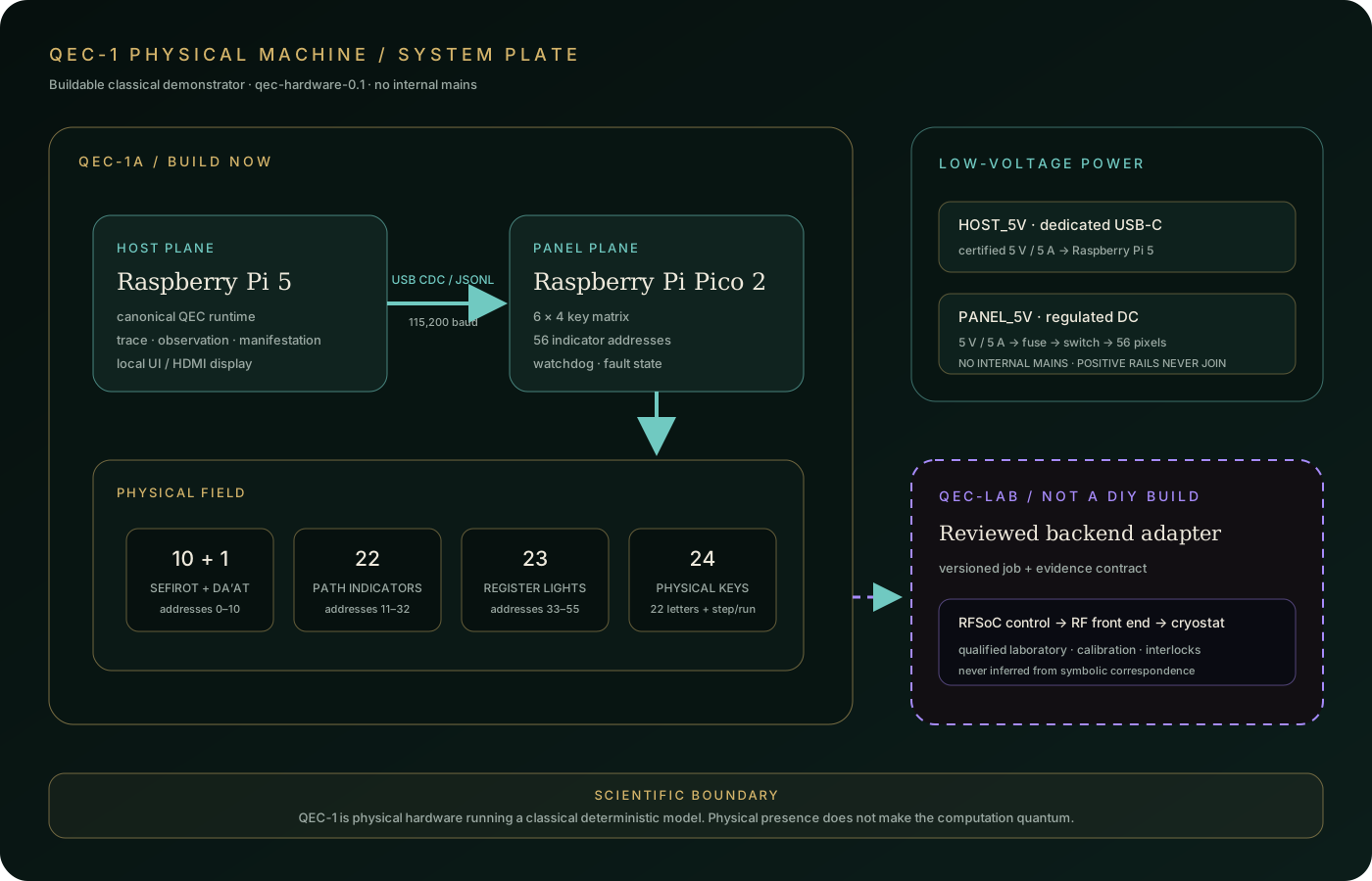
Scientific boundary: QEC-1 is a classical deterministic control-and-display machine. It contains no qubits and makes no claim of superposition, entanglement, quantum error correction, or quantum speedup.
CURRENT BUILD MILESTONE / QEC-1P
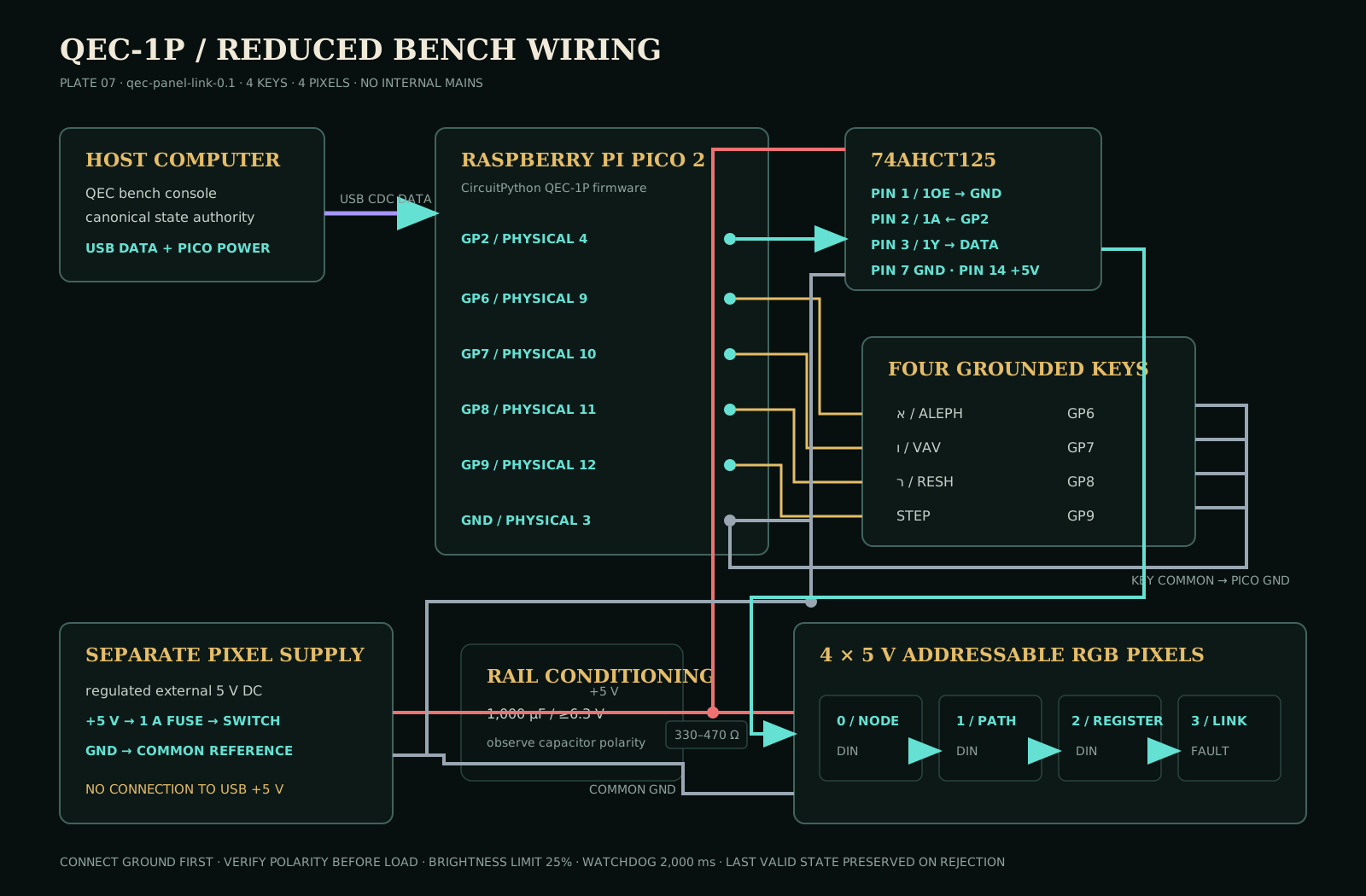
The reduced bench harness is now a complete build gate, not a suggestion. It fixes the Pico pin map, firmware, protocol direction, low-voltage wiring, browser proof sequence, and written acceptance record before the full panel becomes expensive to change.
Pi host, Pico panel controller, Hebrew keys, Tree/path/register indicators, local display, and versioned USB protocol.
Add an electrically isolated FPGA or RFSoC loopback target for protocol and timing experiments. This tier remains classical.
Exchange versioned jobs and evidence with independently operated RF, cryogenic, calibrated quantum-control equipment.
ENGINEERING PLATE SET
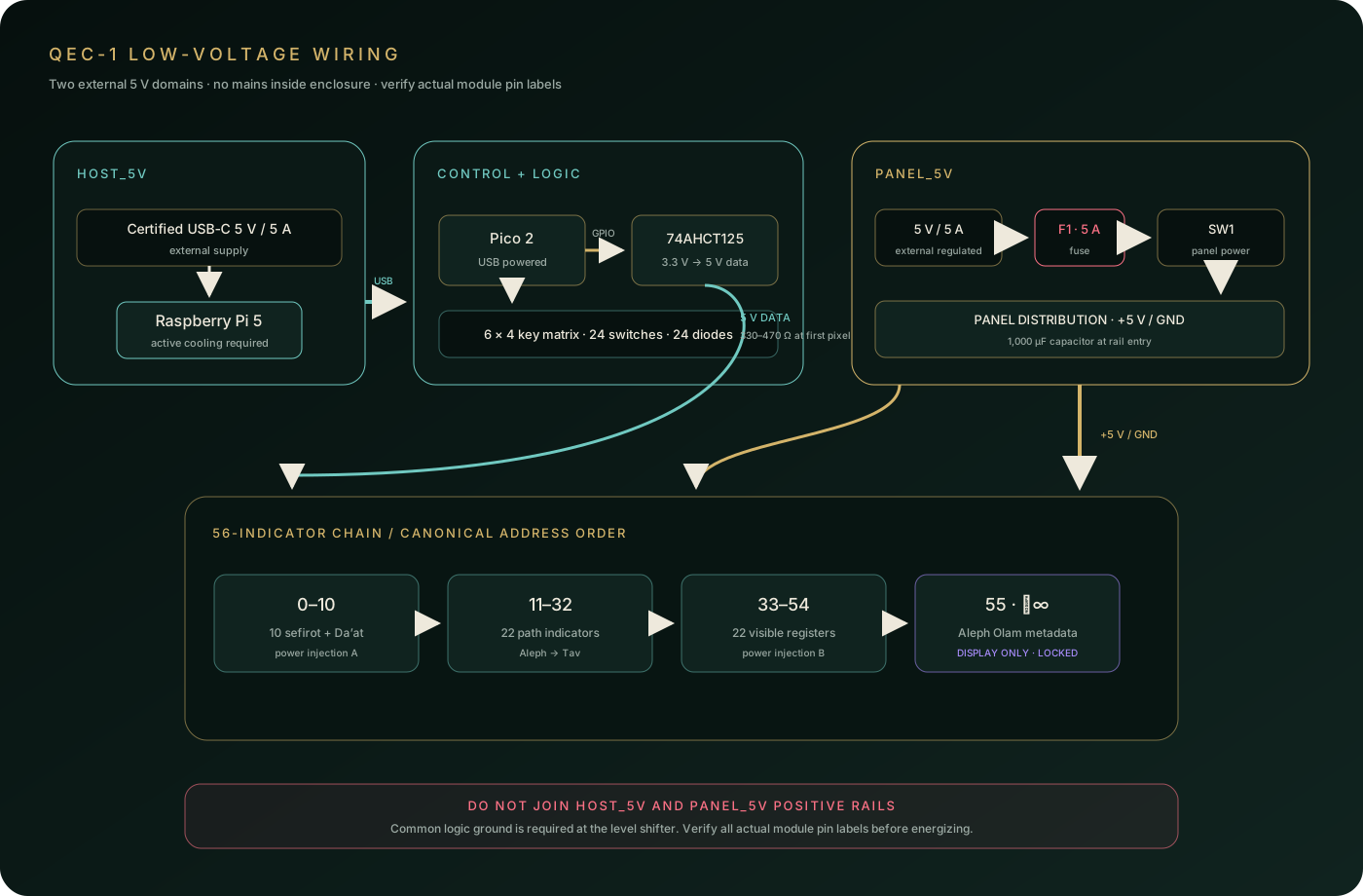
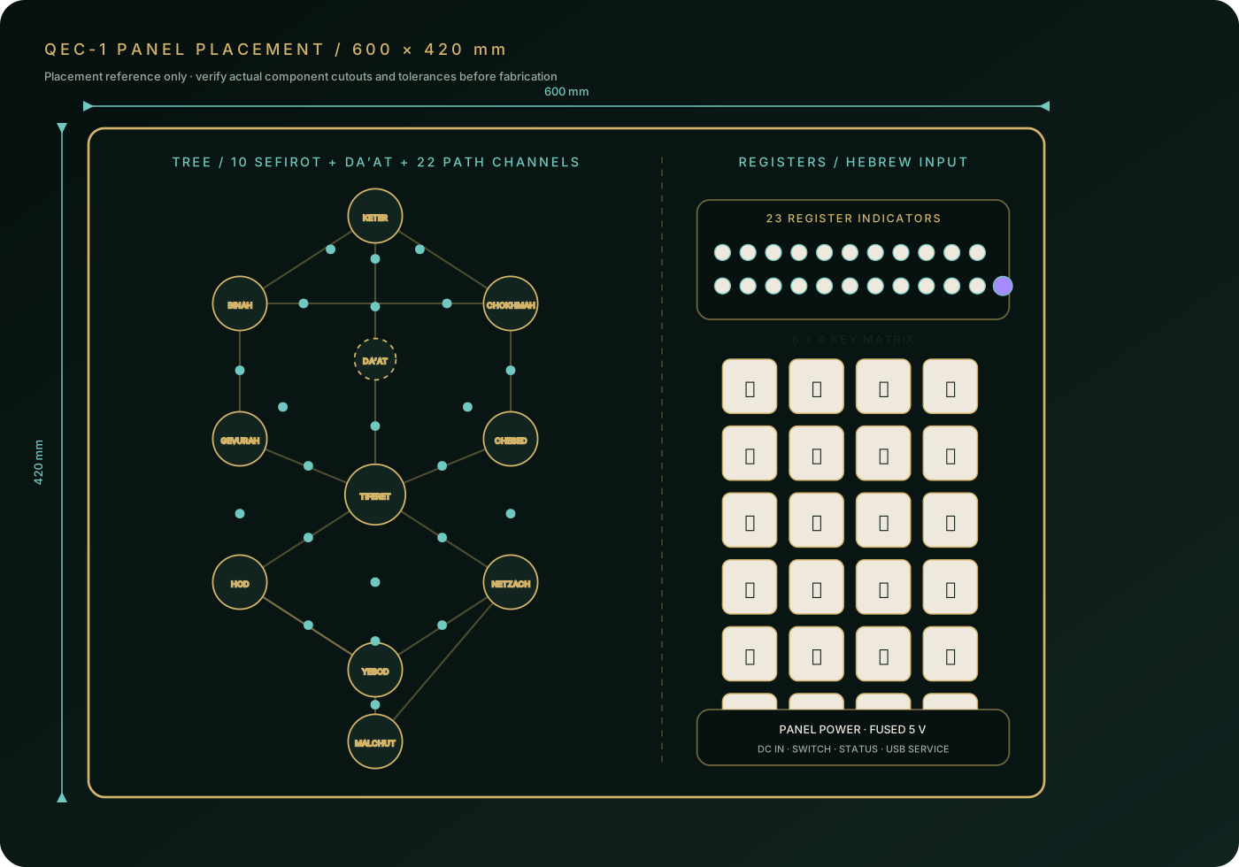
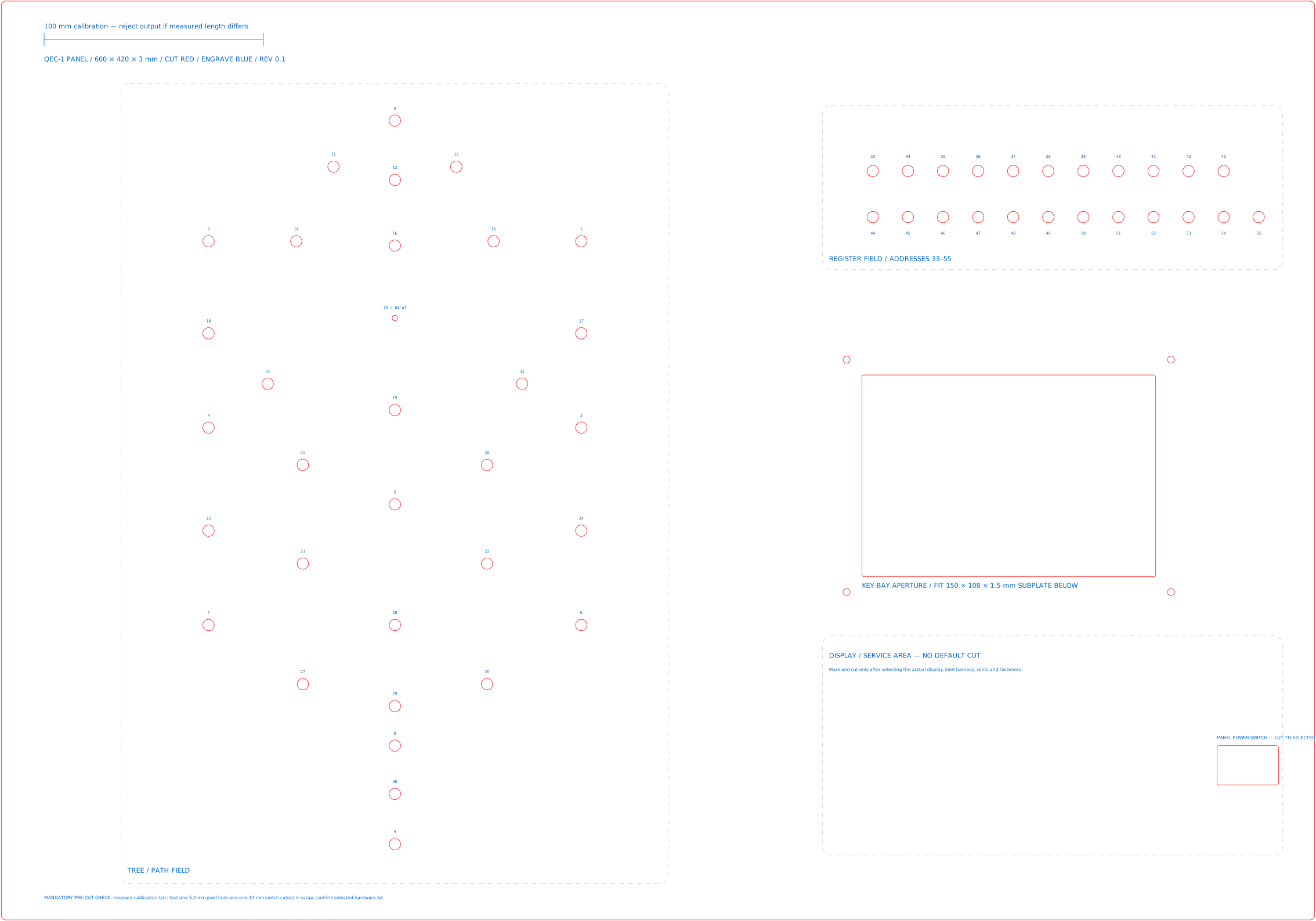
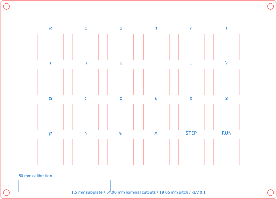
The system boundary establishes ownership. The wiring plate establishes safe low-voltage power and signal paths. The panel plate fixes overall dimensions, field placement, and canonical indicator order. The bench plate proves the reduced harness first. Two full-scale templates control the final panel and its 1.5 mm key subplate.
FIXED PHYSICAL MODEL
The address map is part of the hardware contract: ten sefirot, one Da’at boundary, twenty-two paths, and twenty-three registers. Aleph Olam remains display-only and firmware-locked.
Raspberry Pi 5 runs the canonical engine, interface, trace store, and optional local display. It uses its own certified 5 V / 5 A USB-C supply and active cooling.
Raspberry Pi Pico 2 scans the 6 × 4 diode key matrix, drives indicators through a 5 V logic shifter, and enters a visible fault state when its host link fails.
CORE BILL OF MATERIALS
The versioned BOM names manufacturer parts and a dated reference cost. It is not a live quote: verify stock, price, electrical rating, and every footprint before ordering or cutting.
| QTY | COMPONENT | REQUIREMENT | ROLE |
|---|---|---|---|
| 1 | Raspberry Pi 5 + Active Cooler | SC1112 + SC1148 | Canonical host runtime |
| 1 | Raspberry Pi Pico 2 | SC1631 | Panel controller |
| 1 + 1 | Official Pi 27 W PSU + MEAN WELL panel PSU | SC1154 + GST40A05-P1J | Separate host and panel domains |
| 12 packs | SparkFun 5 mm addressable RGB LEDs | COM-12986 / 60 pixels, 4 spare | Nodes, paths, registers |
| 24 + 24 | CHERRY tactile switches + Vishay diodes | MX2A-G1NB + 1N4148-TAP | 6 × 4 key matrix |
| 1 | TI SN74AHCT125N | DIP-14, 3.3 V to 5 V pixel logic | Pixel data level shifting |
| 1 + 1 | 1,000 µF capacitor + 330–470 Ω resistor | 6.3 V minimum capacitor | Pixel rail and data protection |
| 1 | Fused, switched panel inlet | 5 A DC rating | Panel branch protection |
POWER BOUNDARY
The Pi and panel have separate external 5 V supplies. Logic grounds meet at the level-shifter distribution point; positive rails never meet. A 5 A fuse sits immediately after the panel inlet.
56 × 0.060 A = 3.36 A theoretical full-white indicator load. The panel domain is sized for the full theoretical load while firmware caps global brightness at 25%.
ASSEMBLY SEQUENCE
The final panel is the last irreversible step. A reduced four-key, four-pixel harness must pass protocol, brightness, electrical, and fault tests before full wiring or enclosure cutting.
Pi, Pico, four keys, four pixels, level shifter, fused panel supply, handshake, and fault behavior.
Build four keyed indicator sections, the diode matrix, distribution board, and low-brightness walking test.
Verify a disposable 1:1 template, then fabricate, mount, ventilate, strain-relieve, and label.
Step and run canonical אור seed 09; compare trace hash and manifestation checksum.
RELEASE GATE
The machine is complete only when the physical display reproduces the canonical software result and every electrical or protocol failure leaves the last valid state unchanged.
Component design basis: official Raspberry Pi 5 and Pico 2 specifications; Adafruit’s NeoPixel best practices; and, for the future laboratory boundary only, the open-source QICK control stack.